 |

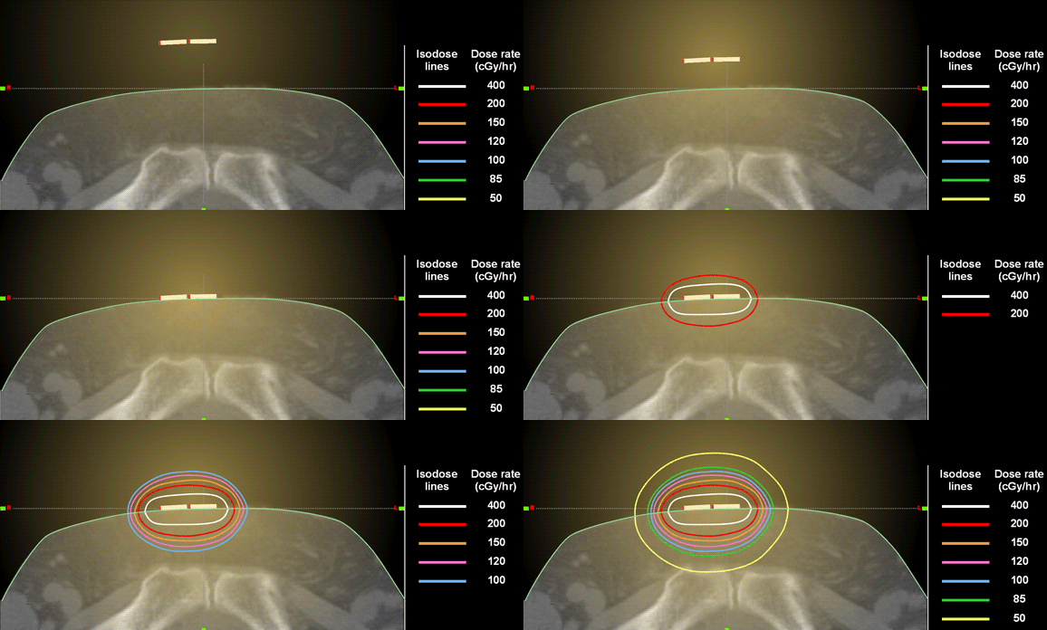
- This CT scan slice shows two Cesium-137 cylinder-shaped radioactive sources placed end to end on skin over the pelvis.
- This example simulates a Radiological Exposure Device (RED) which would cause major skin injury if placed on or near the skin for any significant length of time.
- Since the Cs-137 is encapsulated inside the cylinder, it will result only in radiation exposure, not contamination.
- Actual photograph of a single source (Radiation Product Design, Inc.)
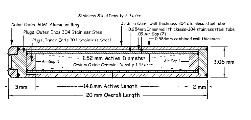
- Cutaway diagram showing how this source is constructed (Radiation Product Design, Inc.)
- The strength of each of the 2 sources in this example = 20 mg Radium equivalent of cesium = 50.6 mCi =1.87x10⁹ Bq.
- Using physical information about each source and anatomic information from the CT scan, a computer program calculated and displayed the seven colored "isodose lines."
- Isodose lines connect points receiving an equal radiation dose or equal dose rates. They are similar to isobars and isotherms on weather maps.
- The seven "isodose lines" on this CT slice connect points with equal dose rates in units of cGy/hour.
- Not shown in this graphic are the estimated dose rates on the skin and a few millimeters below the skin surface, where the dose rate could be as high as 1200 cGy/min.
| Isodose lines |
Dose rate (cGy/hr) |
|---|
| White |
400 |
|---|
| Red |
200 |
|---|
| Orange |
150 |
|---|
| Pink |
120 |
|---|
| Blue |
100 |
|---|
| Green |
85 |
|---|
| Yellow |
50 |
|---|
- These Cs-137 sources emit radiation in three dimensions, not just in 2 dimensions as shown on a single CT slice. Note that radiation is also emitted into air (not shown).
- Connecting all points of equal dose or dose/rate in the 3-dimensional space surrounding a source actually produces an isodose volume or isodose cloud (not shown). The shape of an isodose cloud depends on factors listed below; it may not necessarily be uniform or cylindrical in shape.
- Other key concepts
- Radiation dose decreases as the distance from the source increases (inverse square law).
- Radiation dose also decreases progressively due to attenuation in tissue.
- Since dose is not uniform throughout the irradiated tissue, it is imprecise to describe the radiation dose absorbed as a single number.
- Doses can be expressed in many ways, including the following
- An absorbed dose at a specific point in air, in tissue, on an isodose line, or on the surface or interior of an isodose volume
- A dose rate, i.e., dose/unit time (e.g. 400 cGy/hour as shown by the white line in the diagram above).
- The isodose pattern in this illustration applies only to these specific manufactured Cesium-137 cylinders with the specified radioactive strength, configuration, and shielding.
- The shape of radiation isodose curves varies greatly depending on many factors including
- Radioisotope
- Type of radiation emitted by the isotope (alpha, beta, neutrons, protons)
- X-ray source energies (e.g., 0.14 MV from Tc99m used in nuclear medicine vs 1.2 MV for Cobalt-60 used in radiation therapy for cancer)
- Radionuclide source strength (in units of Bq or mCi)
- X-ray source type (e.g., linear accelerator vs. cobalt therapy)
- Radionuclide source shape (e.g., manufactured Cs-137 cylinder vs. an improvised RED or an RDD explosive fragment)
- Distance of source from skin surface
- Type of tissue directly underlying skin (e.g., air cavity vs. dense bone vs. soft tissue)
- Angle at which radiation enters skin
- Type and thickness of clothing layers

Actual photograph of a single source cylinder (Radiation Product Design, Inc.)

Cutaway diagram showing how source is constructed (Radiation Products Design, Inc.)
|


